Business
How to Avoid Common Mistakes in Injection Molding Design
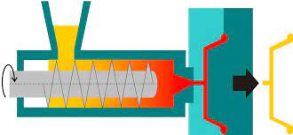
Injection molding seems easy at first glance, but that could be further from the truth. In concept, it is relatively more accessible than other manufacturing processes. You compress liquid plastic resin into an empty cavity.
However, there are a lot of factors in your design to look out for. Many issues might appear on your part if you fail to double-check your design leading to a costly mistake.
That being said, bringing an idea from concept to reality is a difficult task. Whether you are an engineer or an inventor, there are several moving parts you need to consider to get your idea designed, prototyped, and manufactured. Therefore, you must avoid making design mistakes because the process is costly, especially when large quantities are already made.
To avoid common mistakes in an injection molded product design, here are several factors you must consider.
Incorporate Drafts
A draft or taper is an angle incorporated into a design to make it easier to eject the mold during the molding process. One of the common mistakes in injection mold design is not including drafts until it is too late in the design process. Because plastic shrinks towards the center of the part, not taking the draft into account will result in improper ejection that leaves scrape marks.
To avoid this mistake, you must add 1 degree of the draft for each inch of cavity depth, 0.5 degrees for vertical faces, and more than 3 degrees for a shutoff. Also, you must bear in mind that the draft relates to the parting line. With this, the line must be located, so it splits evenly.
Consider Wall Thickness
Injection-molded parts are generally thin, shell-like objects without any deep sections of solid material. Since some areas cool down faster than others, varying wall sections in part designs can cause warping or uneven part properties.
To avoid warping, you must ensure that no areas are abnormally thin since thinner areas cool faster. If possible, your design must have equal and consistent wall thickness. If not, the transition between thin and thick should be as gradual as possible.
Also, it is ideal for thin walls to be no thinner than 40% of the thickness of adjacent walls.
Be Mindful of Undercuts
Often overlooked, undercuts are essential for some part designs. Undercuts are protrusions, recessed areas, or other features that would prevent a part from being ejected from a simple two-part mold. That being said, the undercut in your mold will need to be released first to avoid damaging features of your product.
The more undercuts, the more complex the mold is, leading to more cost. You can eliminate undercuts from your design to make your parts much easier and cheaper to fabricate. If the undercut feature is critical to the part, you can include side-actions, bump-offs, and telescoping shutoffs. But as said earlier, this addition will increase both cost and lead time.
Select Appropriate Materials
Although plastic injection is an advantage in the manufacturing process because of its variety in production, it is essential to consider what material you will use for your part. If the parts are exposed outside, materials with UV stabilizers must be used to prevent cracking. Components needed to take load weight must be composed of materials that include fillers like fiberglass to strengthen the overall product.
For the parts with a bearing surface, the materials should contain an additive like a lubricant to lessen friction. Materials such as polyurethane and long-fiber reinforced plastics cannot accommodate thin walls.
Take Note of Corner Radius
Also overlooked, the corner radius is an essential part of the design. Corner radii make the area more robust, especially in the long term. Also, building radii into a part will eliminate sharp edges, lowering the risk of injuries when handling. Not considering radii will result in additional stress concentrations and possible fractures in the plastic part. And aside from strength purposes, the corner radius makes your plastic part look visually appealing.
Place Parting Lines Accurately
The parting line is the dividing line between the core and cavity molds. The placement of your parting line can affect your molded part’s success and visual appearance. If you fail to have proper placement, issues such as material leaking between the mold core and cavity can arise.
With this, you need to have additional ejection steps that would bring additional cost to your project. To avoid these issues, you should place parting lines along sharp edges. This makes the line less visible and reduces the chances of leaking, among other undesirable effects.
Although CAD software helps you decide the ideal placement of your parting line, your software cannot comprehend the real-world application of your part. Therefore, you must double-check and ensure that your product part design is capable of application.
Key Takeaway
Just like any other manufacturing process, mistakes will be made during the process. However, by considering the factors mentioned above, you can avoid the most common errors in plastic injection molding. To be safe, you can work with experienced design engineers who can help your part design with manufacturing. With this, you can avoid making mistakes and losing time and money.


ETHRA AI Reports Strong Early Momentum as Stage 1 Presale Reaches 11% Completion

Understanding Comparative Negligence in Jacksonville Personal Injury Cases

LiquidWhales Goes Live: The First Hyperliquid Whale Tracker That Grades Every Wallet Net of Fees — and Lets You Copy the Winners in One Click

SolForger Launches as a Non-Custodial Solana Developer Platform for Builders, Creators, and On-Chain Projects

Securing the Future: Jayen Consulting Officially Migrates to a New Digital Domain

Focusing on Compliance, Truoux Advances MAS License Application

Truoux Advances UK FCA License Application, Deepens Compliance Strategic Layout

Truoux Optimizes Risk Control and AML Systems, Accelerating the RMO and DAX License Application Process

Rovum Builds Momentum in On-Chain Settlement Markets

Is Professional Mold Testing Worth It?

Why Small Shipping Boxes Are Becoming the Default for 25-unit Trial Runs

Radio Ads and Personal Spending: Where Prosecutors Allege the Dynamic Money Millions Went

The $34 Million Deception: Where the Guam Charity Bingo Money Really Went

Celeste White’s Influence on Sustainable Agricultural Practices in Napa Valley

Inside the 12-Count Federal Indictment Against Fugitive Darren Anthony Robinson

-
 Business3 days ago
Understanding Comparative Negligence in Jacksonville Personal Injury Cases
-
 Press Release6 days ago
LiquidWhales Goes Live: The First Hyperliquid Whale Tracker That Grades Every Wallet Net of Fees — and Lets You Copy the Winners in One Click
-
 Press Release3 days ago
ETHRA AI Reports Strong Early Momentum as Stage 1 Presale Reaches 11% Completion